New PNNL paper on zinc/manganese oxide energy storage

I’ve had quite a few people email asking what I think about the new paper Reversible aqueous zinc/manganese oxide energy storage from conversion reactions in Nature Energy, by authors at PNNL. Understandable, since I spend a lot of my time talking about Zn and MnO2 for electrical storage. Fair!

PNNL-zinc-manganese-oxide-battery

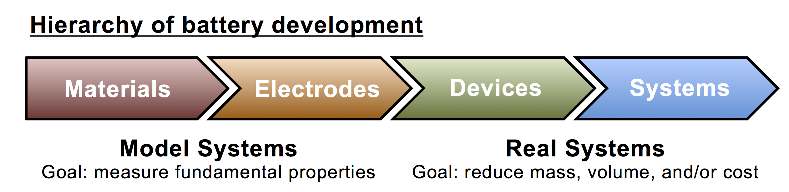
First: unfortunately the work is being marketed (by PNNL) with a terrible graphic of a Platonic ideal supergreen™ battery that sits in a sunlit field and emits rays of light that save the world, but that’s pretty standard for battery research these days. Once the PR department gets ahold of it, you’re waist-deep in pictures of suns, windmills, iPhones, and Teslas. Most people, even most scientists, don’t understand the many levels of hierarchy involved in battery design and engineering, so I try to overlook these kinds of silly Photoshop excursions.

Second: the innovation of the paper is that they are making a rechargeable Zn-MnO2 battery in a mildly acidic electrolyte, and getting good cycle life. The way they’re doing this is by using α-MnO2 as their cathode active material. MnO2 comes in several polymorphic forms, some of which you can see below. (I adapted this figure from a paper by Poinsignon.) They are built from MnO6 octahedra, but can distinguished by the tunnel structures in the crystal.

MnO2 types fig small

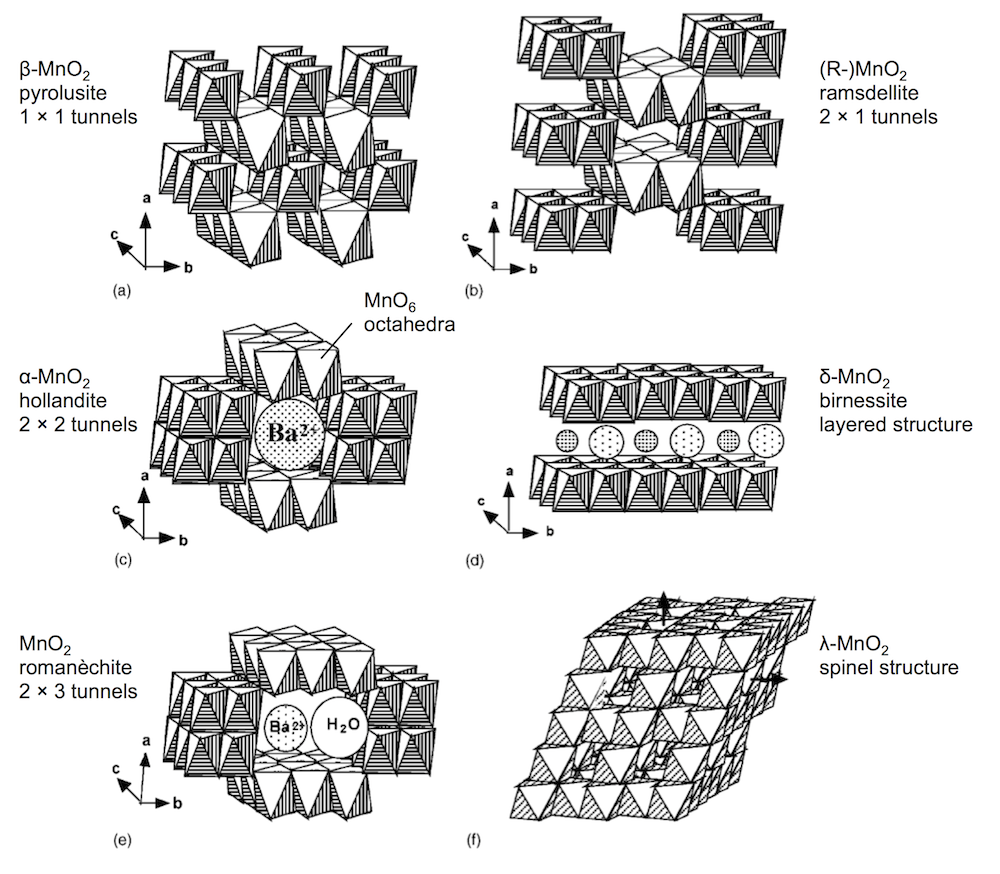
A lot of my recent work has focused on the polymorph γ-MnO2, which is an intergrowth of (a) and (b) above. The PNNL work makes an interesting discovery about α-MnO2: they see the α-MnO2 going through a conversion reaction to MnOOH, which is somewhat unexpected. As you can see in the figure above, α-MnO2 is usually thought of as a host structure, to intercalate guest ions (like Ba2+). They then see that the surface of the MnOOH is coated with a large flake-like material that originates with the sulfate electrolyte, ZnSO4[Zn(OH)2]3 · xH2O. In this respect, the reaction is a bit reminiscent of a lead-acid battery, which also involves a sulfate film.

The paper is very interesting in that it provides unexpected evidence of α-MnO2 acting in the manner of a conversion reaction. (And that’s why that term is important and shows up in the paper’s title.) Also the zinc hydroxyl sulfate flake-film is a tantalizing look at what could be a very complex cathode reaction. And I’m a sucker for complex electrochemical reactions, as I hope you know. The test bed for the research was a CR2032 form factor, which is the kind of battery that goes in my running watch. So, the picture the PR machine and the science press are painting (with that world-saving battery up above) is a bit overblown, but the electrochemistry research underpinning this paper is extremely interesting, and I hope to see more.

Manganese dioxide: the almost perfect cathode

The year is ending, and I’m wrapping up some researching findings for publication. And some exciting news: once the new year starts I’m headed to NSLS-II to use the cutting edge submicron resolution spectroscopy beamline for some experiments on a brand new battery chemistry.

First I’d like to pause to reflect on what I’ve spent the last couple years on: shallow-cycled manganese dioxide (MnO2) as a cathode material. Specifically, why we need it:

  • It’s extremely cheap
  • It’s extremely safe
  • It’s found all over the world
  • It works in aqueous (water-based) batteries

These facts make it ideal for an emerging battery market, which is large-scale, grid-level battery storage for buffering solar and wind power. This storage market will be fundamentally different than the last major new market, which emerged in the 90s: that for portable computing and electronics. Portable computing requires high energy density, with cost and safety being secondary. In contrast, the planet-wide battery deployment needed for a green (i.e. solar) future will live and die on battery cost and safety, with energy density being secondary.

MnO2 the almost perfect cathode

This leads to the almost in the title of this post: MnO2 is perfect for grid-scale battery storage (it even has high energy density) except its crystal structure breaks down at the end of discharge. This is shown in the X-ray diffraction data above. The three prominent MnO2 reflections shift to lower values of 1/d as the electrode discharges, because protons are inserted into the lattice causing it to expand or dilatate. Reaching the end of discharge, these reflections spread out and become dull (or somewhat amorphous) as other manganese oxides form, including the major discharge product groutite (α-MnOOH). Upon charge, groutite is converted back to MnO2, and the lattice shrinks as protons are de-inserted. We’ve gotten the MnO2 lattice back, but the problem is the “other” manganese oxides that formed at the end of discharge and are irreversible. Some reflections of hausmannite (Mn3O4) are now found in the electrode. Haumannite is highly resistive, and if too much forms, the electrode will fail. It doesn’t take many cycles. A few like this will do.

With funding from ARPA-E we developed a Zn-MnO2 battery that can cycle thousands of times, by limiting the discharge depth and not going all the way to 0.9 volts, as was done above. (That of course raises cost, but since zinc and manganese dioxide are cheap, the economics still come out in your favor.) Even then, we found that Mn3O4 (and its relative ZnMn2O4) still ends up forming around the MnO2 particles, giving them a resistive coating. Thankfully this doesn’t kill the battery, but it does mean there is a limit to how deeply you can discharge this way. However, by doing some very fundamental forensic-type experiments, resolving the manganese oxide crystal structures within undisturbed batteries, we learned something interesting. There are some important differences between the manganese oxides you see in operando (like those above) and the ones in a battery that has aged a while. In other words, the Mn3O4 seen above isn’t completely formed yet, and that suggests that perhaps its formation can be reversed, at least before too much time has passed. And that … is what we’ve been trying. Stay tuned for more on that.

Hierarchical characterization of batteries

Electrochemistry is fundamentally an interfacial science, dealing with reactions that happen at the interface between an electron conductor and an ion conductor. In many cases, including most practical batteries, this is a solid-liquid interface. Most batteries are consequently designed to be composed largely of interface. Often compressed particles of active material make up the electrodes and liquid electrolyte fills the pore space between the particles. The goal of battery engineering revolves around questions of either energy or power, and what value of these can be achieved in a device of a given mass, volume, or cost. Thus some metrics of battery success dealing with energy are: specific energy (Wh/kg), energy density (Wh/L), or capital cost ($/kWh). High specific energy is crucial for automotive batteries, while low capital cost is most important for large, stationary batteries at the building or grid scale.

Hierarchy of battery development

Another fundamental feature of electrochemistry is that it by necessity involves the interplay of two electrodes, an anode and a cathode. Experimental techniques exist to test electrodes in isolation, but in practical devices such as batteries the electrodes usually interact. Device performance is determined not only by the performance potential of each electrode, but also by the effect of each electrode on the other. Because of this and the need to maximize interface, battery design is hierarchical (see fig. above): (i) active materials are chosen due to their voltages and rate capabilities; (ii) the active materials are formed into useful electrodes, which may have high surface area; (iii) the two electrodes are integrated into a device; and (iv) devices are connected (in series or parallel) to form a system, if needed.

This hierarchy requires specialized characterization at every level. There has long been an established toolkit for electrochemical materials characterization, but true device-level characterization is only now coming into its own as techniques are developed to collect microscopic data from within sealed batteries. Device-level knowledge beyond voltage/current (E/I) data is extremely powerful and promises to advance understanding into the complex mechanisms that occur inside cycling batteries. An overreliance on materials-level characterization ignores conditions arising from device-level aspects. One example is electrolyte concentration at the outer radius of a AA battery, which falls from its initial value during discharge, and is thus different than the same concentration in a D battery, which rises due to a much longer transport path to the anode. With materials-level characterization there is also the danger for a fallacy of composition, in which remarkable capabilities of the materials are inferred to the device without justification, based on a misunderstanding of battery design principles.

Dendrites: Zinc and Lithium

I just got back from the spring Electrochemical Society conference in Chicago, where I was presenting in a session on Dendritic Growth and Interface Stability. Several people showed in operando images of dendrites growing in real time. One in particular I liked a lot was by Layla Mehdi at PNNL … she has a specialized test cell to observe lithium dendrites by transmission electron microscopy. I’ve done a lot of work on dendrites, and what I care most about is why dendrites form. While I was watching all these great movies of dendrites growing, I wondered something I often wonder: why do some dendrites look like they grow from the tip, and some from the bottom?

Dendrites can be the result of multiple mechanisms. They’re often a mass transport effect, but sometimes not. If you flow electrolyte over dendrites, you can directly observe the kinetic growth limit at their tips (plug for my paper about about that), but the non-growing locations aren’t really mass-transport starved … rather, they are in locations of low overpotential. So, that all makes sense, but still sometimes I’m baffled. Consider the two movies below …

The first one (this is my data from the paper above btw) shows zinc dendrites growing in a 1 mm wide flow channel, with alkaline electrolyte flowing from top to bottom. Essentially this is a model of a zinc flow battery. Growth here is potentiostatic (2.5 V) with oxygen generation at the electrode on the right. The important thing is watch the tips. That’s where the growth is. The bases of the dendrites are static.

Here is an analogous movie of a lithium dendrite growing in a flow channel. This was taken by Owen Crowther (paper here), who’s now working at Eagle Picher. If you focus on the dendrite tip, it doesn’t look like there’s any action there. Growth seems to come from the base (or middle). But that would be the location of lowest overpotential and lowest mass transport, so there must be something catalytic happening. Perhaps it’s because of a locally thin SEI layer.

Dimensional analysis of batteries

Now that high performance batteries are a big part of our daily lives, powering our cell phones and portable computers, we naturally want to spend less time waiting for batteries to charge up. This has prompted the search for ultrafast batteries. We would like batteries that can cycle at high currents, either discharging or charging in no time. Perhaps you’d like to charge your cell phone in under a minute, or you’d like to charge your EV in the same few minutes it takes to fill up with gasoline.

Either way, fast batteries are an engineering challenge. A good way to think of this is that it’s fairly easy to make a small battery that can cycle rapidly, but as a battery becomes larger, approaching the size it takes to power your phone or car, it gets more challenging. The way to understand this is to look at dimensional analysis.

Dimensional analysis example

Dimensional analysis is the engineering concept used to understand the scale or size of something, and was discovered by Galileo. Basically, to make size not matter, you have to eliminate all dimensionality in a problem. To do this you multiply/divide the important constants in the problem to make the dimensions cancel out.

Up above is a dimensionless number for a structure, which involves: the yield strength and density of the structure materials, the gravitational constant (gravity pulls down on the structure), and the structure size, which is L, a length like the height. Consider this: is a matchstick model of Notre Dame Cathedral a fair model of the real Notre Dame cathedral? And if so, does it mean you could make the real Cathedral out of wood too?

The answer is no. The matchstick model is not at all like the real Cathedral, because while size does change between the two, gravity does not. A successful matchstick model means you could build the real Cathedral out of wood … only on a smaller planet with a lower value of g.

Dimensional analysis of a battery

Dimensional analysis of a battery is similar to that of the Cathedral above. Imagine a small research-scale battery you might work with in a lab, and then imagine a practical battery based on it. The practical battery has been developed and scaled-up to provide the power and energy required by the application. Scaling up a battery almost always involves thickening the electrodes, and we will call this “increasing L.” The important length scale of an electrode is usually the thickness in the same dimension as current flow.

I’ve written previously about reaction rate distributions in battery electrodes (here and here). The dimensionless number δ (or John Newman’s number) tells you how balanced the reactions in a battery electrode are. When L increases, it tells you that something else has to decrease, like current I, if you want to keep δ the same. This means in general a small battery will charge fast and a large battery will charge slowly.

This is unless the other parameters in δ change accordingly to keep behavior the same … for example the porosity could be increased and that would increase the pore conductivity or κ and therefore decrease δ. But usually this goes in the opposite direction: as you scale up typically you want to achieve higher active material loading, pushing you to decrease porosity and thus decrease κ and increase δ. In fact, almost every decision you make during scale-up forces you to increase δ overall.

For this reason, the very first research decision you should try to make is to set L at the same value in your small battery that you will need in the final device. That way it becomes easier to understand scale-up, and you can extrapolate research results to real-world situations. When analyzing a fast battery, first check L and see whether scale-up will require it to increase.